U.S. Manufactured SolarEdge Power Optimizer C651U: Maximizing Efficiency with Fewer Strings

Table of contents
- Introduction: Solar Design with Fewer Strings and Commercial Solar Optimizers
- Technical Specification of C651U Power Optimizers
- Fusing and Cable Sizing with C651U Systems
- When to Use More Than Two Strings
- Three Wiring Options for Three-String Systems
- Conclusion: Optimized for Performance, Simplicity, and Scale
Introduction: Solar Design with Fewer Strings and Commercial Solar Optimizers
The SolarEdge C651U Power Optimizer enables higher string capacity and streamlined wiring in commercial PV systems. This guide reviews technical specs, design scenarios, and NEC-compliant wiring practices to ensure optimal PV safety and system performance.
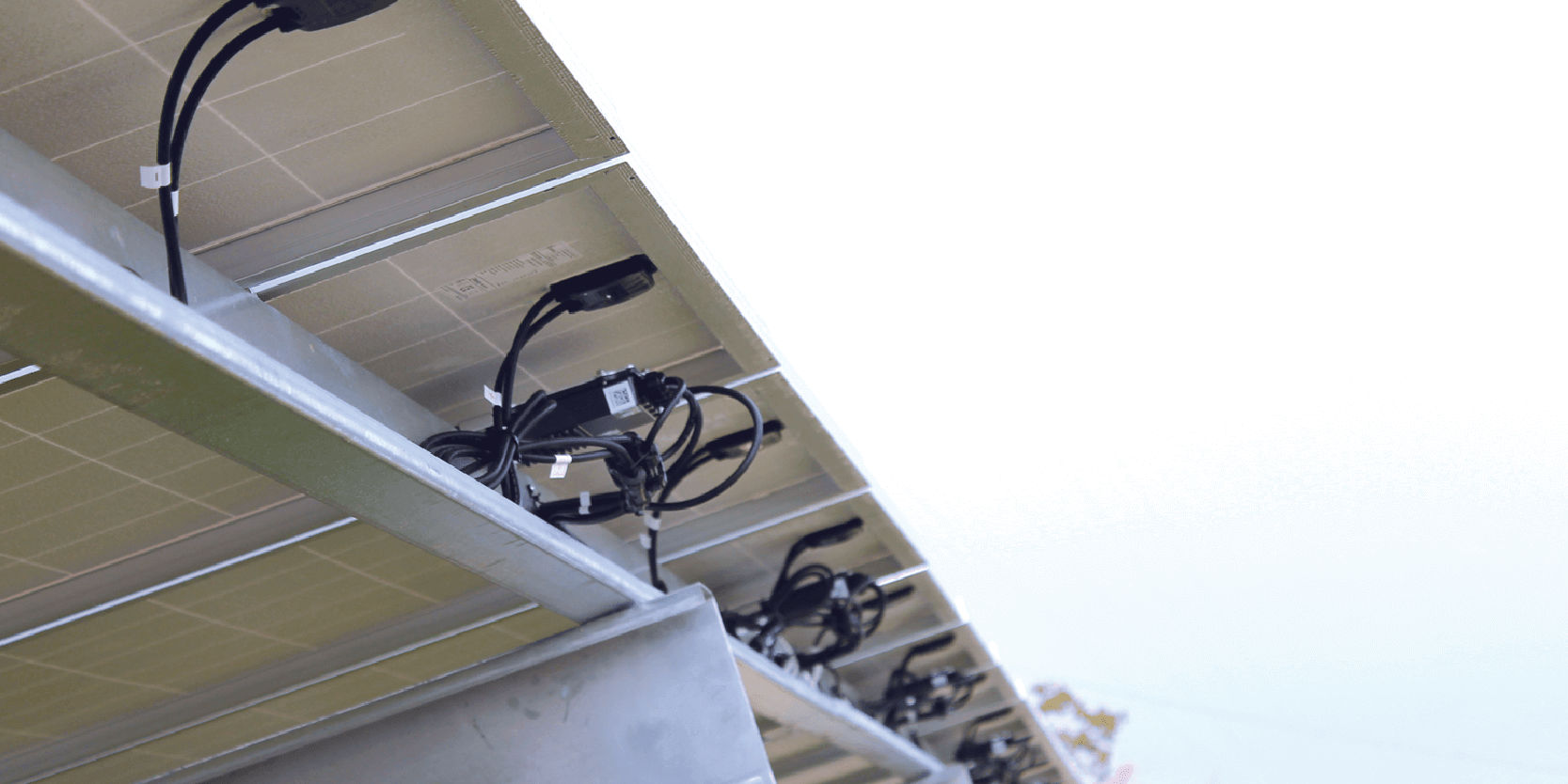
The new C651U, a domestically manufactured Power Optimizer from SolarEdge, includes a significantly higher maximum output current rating and string power capacity than previous generations. In most cases, this advancement allows for simpler system design and a reduction in the number of PV strings needed. This article addresses edge-case considerations when designing systems with C651U Power Optimizers.
Technical Specifications of C651U Power Optimizers:
- Rated Input DC Power: 650W
- Maximum Short Circuit Current (Isc) of Connected PV Module: 20A DC
- Maximum Output Power: 650W DC
- Maximum Output Current: 24A DC
- Maximum Output Voltage: 60V DC
- Maximum String Power at 480V AC: 30.4kW DC
- Maximum String Power at 208V AC: 15.6kW DC
Previously, S1201 Power Optimizers were capped at 23kW DC per string, typically resulting in designs with three or four strings per inverter unit. With the C651U, that limit increases to 30kW, enabling two-string designs in most cases. This reduces installation complexity and cost, resulting in up to a 66% reduction in total strings compared to traditional string inverter systems.
Fusing and Cable Sizing with C651U Systems
In most two-string cases, string fusing is not required under NEC 690.9(A)(1). With a max output of 24A per string, using #10 AWG PV wire remains a safe, straightforward solution. This option avoids the need for upsizing, which helps keep the design and installation simple.
- Standard Ampacity (Copper Wire rated 90°C):
- #10 AWG = 40A
- #8 AWG = 55A
- Ground Fault Condition: With C651U Power Optimizers, the maximum string current is 24A. In a ground fault condition, the maximum current that could back feed is n-1, where n is the number of strings. For two strings, this would be 24A, and per NEC Table 310.16, a #10 wire can handle up to 40A at 90°C, so upsizing is not required.
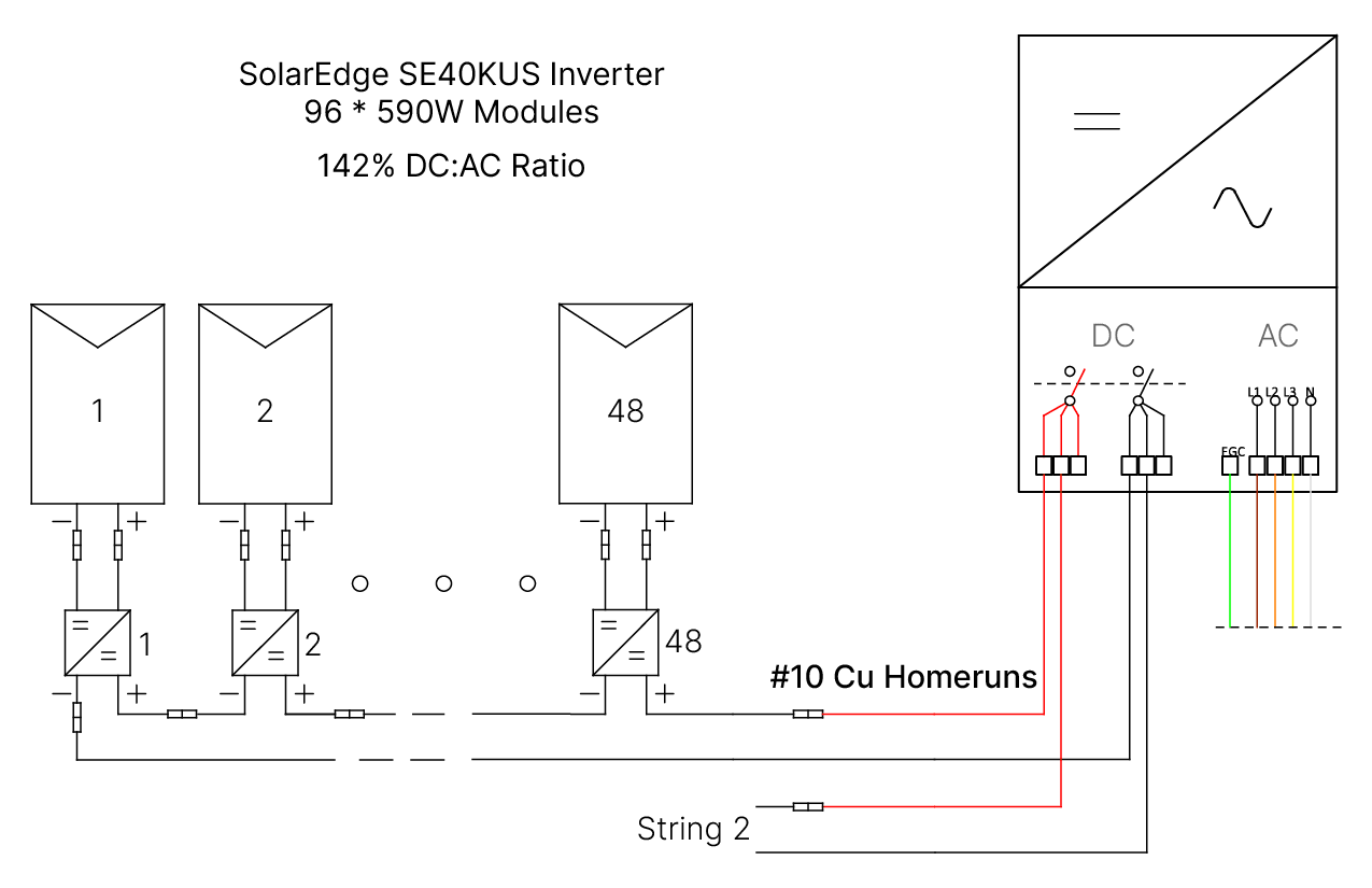
Figure 1: Sample Wiring Diagram for 2-String System
Figure 1: Sample Wiring Diagram for 2-String System
When to Use More Than Two Strings
While two-string designs typically offer maximum benefit, some scenarios may justify three or more strings:
- High DC/AC ratios, where loading more than 2 × 30kW DC per inverter unit is desired
- Low wattage modules, where the absolute limit of 57 Power Optimizers doesn’t reach the 30kW max power limit per string.
Table 1 below highlights the edge case scenarios that may require going beyond the two-string design when using the C651U with a 40kW inverter unit.
|
DC:AC Loading Ratio |
||||||||
| Module |
1.0 |
1.1 |
1.2 |
1.3 |
1.4 |
1.5 |
1.6 |
1.75 |
| 450W |
2-string |
2-string |
2-string |
3-string |
3-string |
3-string |
3-string |
3-string |
| 500W |
2-string |
2-string |
2-string |
2-string |
2-string |
3-string |
3-string |
3-string |
| 550W |
2-string |
2-string |
2-string |
2-string |
2-string |
2-string |
3-string |
3-string |
| 600W |
2-string |
2-string |
2-string |
2-string |
2-string |
2-string |
3-string |
3-string |
| 650W |
2-string |
2-string |
2-string |
2-string |
2-string |
2-string |
3-string |
3-string |
Table 1: Systems that would use two vs three string design with C651U and 40kWac Inverter Units
Three Wiring Options for Three-String Systems
Using NEC section 690.9, three strings in parallel at 24A each would mean a fault condition of 48A, avoiding the use of overcurrent protection devices (OCPD) such as fusing in that scenario requires the maximum ampacity of home run cable (including any derates) to be above 48A.
SolarEdge offers three practical solutions to address these wire-sizing challenges (assuming ambient temperatures of 40°C or less):
#10 PV Wire with Three Strings (Inline Fusing)
In systems using three strings #10 PV wire remains viable when paired with a 30A inline fuse. This fuse limits the maximum current through the PV wire, keeping it within the 40A capacity at 90°C. The inline fuse provides overcurrent protection, ensuring the conductor is safeguarded against fault currents exceeding its rated ampacity.

Figure 2: Sample Wiring Diagram for 3-String System Using In-line Fusing
Figure 2: Sample Wiring Diagram for 3-String System Using In-line Fusing
Staubli produces in-line fuses that are MC4 compatible and will integrate with SolarEdge Power Optimizers: https://www.staubli.com/global/en/electrical-connectors/products/renewable-energy-solutions/in-line-fuse.html
#8 PV Wire in Cable Trays with Three Strings
For installations requiring three strings #8 PV wire can be effectively used in cable trays. This approach avoids derating complications associated with conduit and ensures compliance with NEC regulations while offering flexibility in system layout.
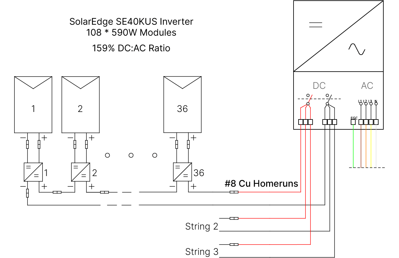
Figure 3: Sample Wiring Diagram for 3-String System Using Upsized Homerun Conductors
Figure 3: Sample Wiring Diagram for 3-String System Using Upsized Homerun Conductors
- Cable Tray Advantage: In cable trays, no derate factors are applied for the number of current-carrying conductors. The ampacity of #8 copper wire at 90°C would be 50.1A, which is sufficient for three strings in parallel.
- Conduit Derate Factors using NEC table 310.15(C)(1): When in conduit a derate factor must be applied to the ampacity of the conductor. For #10 wire at 90°C, the ampacity would be 29.12A after derating, which is insufficient for three strings. Upsizing to a #8 AWG or #6 AWG might be necessary.
Centralized Configurations with SolarEdge Single DC Input (on roof-top or at ground-level):
For systems where inverters are centralized, SolarEdge’s Single DC input option offers another solution. By using an external combiner box with integrated fusing, OCPD requirements are accounted for.
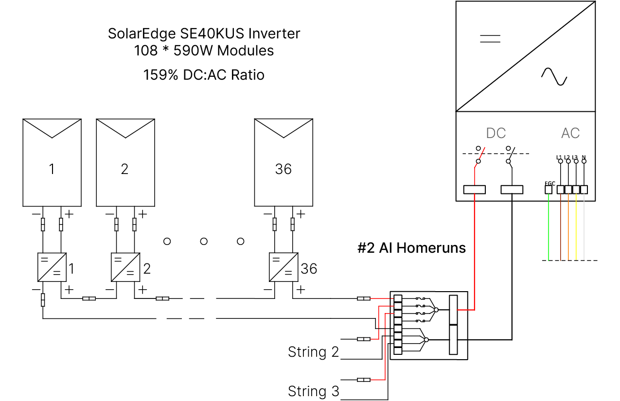
Figure 4: Sample Wiring Diagram for 3-String System Using Combined DC Input
Figure 4: Sample Wiring Diagram for 3-String System Using Combined DC Input
Voltage Drop Management: A common challenge is voltage drop, especially when PV homeruns exceed 300ft. SolarEdge inverters limit input current to 48A, which is the current level that should be used for voltage drop calculation for a combined home run (with two or more strings). When PV strings are kept separated for homeruns the optimizer output current (24A) should be used for voltage drop calculations. This mitigates voltage drop concerns and allows for extended homerun lengths without compromising performance.
Conclusion: Optimized for Performance, Simplicity, and Scale
The SolarEdge C651U Power Optimizer enhances commercial PV design by allowing higher string capacity and reducing total string count -- streamlining installations while cutting labor and material costs. With flexible wiring options and NEC-compliant configurations, it empowers designers to build smarter, more scalable systems. Proudly manufactured in the U.S., the C651U reflects SolarEdge’s continued leadership in advancing commercial PV technology.
Note: All National Electrical Code (NEC) references in the above document are made to the NFPA 70 NEC 2023 Series.
FAQs
How do I calculate voltage drop for systems with C651U optimizers?
For combined homeruns (e.g., from a combiner box), use 48A for voltage drop calculations (inverter max input). For separate homeruns, calculate based on 24A per string (optimizer max output).
Are there design tools or templates available for C651U systems?
Yes! Visit the CC&I Marketing Portal for design templates, datasheets, and planning resources tailored to C651U-based projects. Plus, SolarEdge Designer is a free online tool to customize your system build and validate different equipment options.
What is the maximum distance for a PV string homerun with SolarEdge?
While voltage drop considerations are likely to affect the distance between PV array and inverter, the option to change cable size can usually mitigate the voltage drop concern. The absolute maximum string distance is defined by the power line communication (PLC) functionality of the inverter and is dependent on the inverter model. For most three-phase inverters a total round-trip length of 2300ft (700m) is allowed for each connected PV string.
How does a rooftop SolarEdge system stay below 1000V DC with strings of up to 57 modules?
SolarEdge systems for rooftop applications do not operate the strings above 1000V DC. Our 480V AC inverters operate at a fixed DC voltage of 850V DC. The PV modules are not connected in series directly, so voltage is not the sum of all modules on the string. Each PV module is connected to one Power Optimizer, with a maximum input voltage of 80V DC. SolarEdge optimizers act as buck-boost converters, for long strings, the optimizers are operating in buck mode, reducing the DC voltage on the output side of the optimizer and increasing current. The optimizers on one string are connected in series and will operate such that they maintain a constant 850V DC in total.
What is the difference between the three maximum string power levels on the optimizer data sheet? Why does max power per string increase with more strings in parallel?
Maximum continuous power per string – This rating is the actual maximum power that can be delivered by the optimizers, as they limit on current and operate at fixed output voltage.
Maximum allowed connected power per string (one string) – This rating is roughly 15% above what the optimizer can actually deliver. In max power conditions the optimizer would limit current to the maximum output current value. However, an oversizing ratio of 115% will translate to almost no annual clipping at the string level. Any higher ratio would mean the average current per string is often above the max optimizer current. Consistent current limiting on the optimizer side is not a good design practice.
Maximum allowed connected power per string (two strings or more) – This rating shows that there is now enough power and current per string that the inverter will be doing the current limiting, so increased string oversizing is permissible.


